
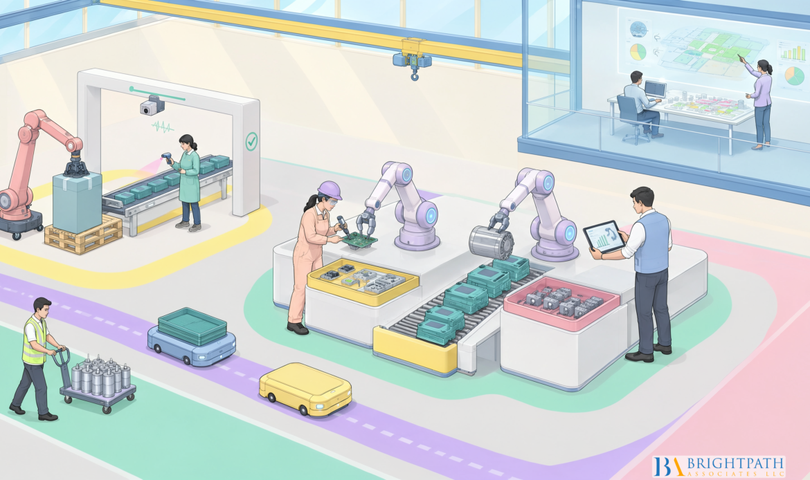
Optimizing Factory Layouts for Collaborative Robotics Integration for machinery Industry requires a fundamental shift from traditional physical isolation toward shared, highly coordinated #ProductionSpaces. As machinery manufacturers adapt to tight floor space, changing product mix, and persistent technical workforce constraints, modernizing shop floors demands more than dropping a cobot next to a computer numerical control (CNC) machine tool. We must treat the robot arm, end effector, workpiece, machine tool, chip conveyor, maintenance clearance, and human access paths as a single, dynamic system. At BrightPath Associates, we evaluate these automation decisions not only as mechanical and spatial engineering problems, but also as strategic leadership challenges that require aligned operational talent and clear organizational execution.
Table of Contents
• Architectural Principles of Collaborative Robot Cell Design
• Spatial Workflows: Kinematic Configurations and Footprint Strategies
• Engineering Safety, Compliance, and Hazard Mitigation
• Strategic Leadership, Executive Alignment, and Talent Capabilities
• Frequently Asked Questions
• Resources and Citations
Key Takeaways
- Integrated System Perspective: A collaborative robot arm is not inherently safe on its own; cell safety and throughput depend entirely on the total layout, including tooling, machine doors, chip disposal, and surrounding fixtures.
- Clear Maintenance Envelopes: Failure to build dedicated service clearance into the initial layout leads to severe operational bottlenecks, manual bypasses, and extended recovery downtime.
- Flexible Kinematic Selection: Choosing between fixed mounts, mobile carts, and linear seventh-axis tracks requires balancing reach coverage, setup changeover times, and zone scanner complexity.
- Workforce and Leadership Alignment: Successful automation deployment requires operations leaders and automation engineers who can bridge engineering standards with broader growth strategies for machinery manufacturers.
Architectural Principles of Collaborative Robot Cell Design
Mapping the Integrated Collaborative Workspace
Designing a collaborative machinery cell begins with defining the exact physical boundary where humans and robots interact. In industrial machinery production, this area extends beyond the operating radius of the robot arm. The collaborative workspace encompasses the robot arm, the end-of-arm tooling (EOAT), raw material stage tables, finished part buffers, and the clearance zones needed by human operators to load pallets, execute quality measurements, or perform routine machine adjustments.
When mapping these spaces, we must establish explicit visual and mechanical zones on the plant floor. Demarcation must be visible, utilizing contrasting epoxy floor coatings or durable line marking to communicate operating zones to shop floor personnel. The workspace layout directly controls human access routes and defines where protective speed reductions or safety-rated stops must trigger.
+————————————————————————-+
| PROTECTED OUTER ZONE |
| +——————————————————————-+ |
| | REDUCED SPEED / WARNING ZONE | |
| | +————————————————————-+ | |
| | | COLLABORATIVE WORKSPACE | | |
| | | +——————-+ +——————-+ | | |
| | | | Machinery / | <==========> | Collaborative | | | |
| | | | CNC Machine | Part Pass | Robot & Fixtures | | | |
| | | +——————-+ +——————-+ | | |
| | +————————————————————-+ | |
| +——————————————————————-+ |
+————————————————————————-+
Integrating Machine Tools, Tooling, and Peripheral Equipment
#IntegratingCollaborative robotics into machine tending or heavy component assembly demands rigorous attention to peripheral equipment. A machine tool door opening automatically, a pneumatic vise clamping a heavy casting, or an automated chip conveyor running on a timed cycle each introduces distinct mechanical pinch points and energetic hazards.
According to ISO 10218-2:2025 standard specifications, safety requirements apply to the complete industrial robot application and robot cell, encompassing all integrated machines, auxiliary tools, and safeguard mechanisms. If an operator enters the cell to inspect a finished bore while the cobot is idle, an unguarded secondary device—such as an automated part wash tank or air-blow clearance nozzle—can present severe collision or injection hazards. Consequently, layout engineering must incorporate all peripheral devices into the safety circuit, interlocking automated doors and indexing tables with presence-sensing devices.
Balancing Power, Force, Speed, and Separation Parameters
To operate without physical perimeter fencing, collaborative applications rely on specific operating modes governed by international technical standards. Selecting the appropriate mode governs the physical footprint and throughput potential of the manufacturing cell:
- Power and Force Limiting (PFL): The robot monitors motor currents and joint sensors to keep contact forces below precise biomechanical thresholds. PFL allows continuous human presence alongside the robot, but requires lower axis speeds and smooth, rounded tooling contours.
- Speed and Separation Monitoring (SSM): Safety-rated laser scanners or optical sensors establish dynamic protection zones around the robot. As an operator approaches, the robot incrementally reduces velocity, coming to a safety-rated stop before contact occurs.
- Safety-Rated Monitored Stop (SRMS): The robot operates at full production speed when isolated, but immediately triggers a non-disruptive, powered stop when a human opens an access gate or steps into the active cell footprint.
- Hand Guiding: Operators manipulate the robot arm directly using force-torque sensor handles, commonly utilized for heavy part positioning or teaching complex motion paths.
As detailed in Omron’s collaborative robot safety documentation, specific force and speed monitoring parameters depend heavily on application data, operator contact area, workspace hazards, and surrounding physical equipment. Consequently, deploying the exact same cobot model across two separate machine tools can demand radically different safety zone clearances and speed limits if one cell presents sharper workpiece edges or tighter surrounding structures.
| Collaborative Operating Mode | Safety Sensing Requirement | Maximum Typical Velocity | Footprint Space Impact | Ideal Machinery Application |
|---|---|---|---|---|
| Power & Force Limiting (PFL) | Internal torque sensors, force-limiting joints | 250 mm/s to 500 mm/s | Minimal (no physical buffer zones) | Small part machine loading, polishing, light assembly |
| Speed & Separation Monitoring (SSM) | Safety laser scanners, 3D radar/vision systems | 1,000 mm/s to 1,500 mm/s | Moderate to Large (requires deceleration clearance) | Heavy casting handling, dual-machine tending, palletizing |
| Safety-Rated Monitored Stop (SRMS) | Interlocked light curtains, pressure mats | Full industrial speed (>1,500 mm/s) | Medium (requires physical entry boundaries) | High-speed machining, batch loading with periodic manual interjections |
| Hand Guiding | Direct-interface force/torque wrist handles | Very Low (operator controlled) | Minimal (localized to guidance workstation) | Heavy tool changing, crane-assisted alignment, teaching |
Spatial Workflows: Kinematic Configurations and Footprint Strategies
Fixed, Mobile, and Linear Seventh-Axis Mounting Strategies
Choosing how to mount a collaborative robot alters factory floor traffic, changeover efficiency, and mechanical reach coverage. Machinery manufacturers generally select between three core architectural mounting configurations:
• Fixed Pedestal Mounting: The cobot is bolted directly to the shop floor or integrated onto the base frame of the machine tool. This layout maximizes positional repeatability and minimizes calibration requirements, making it ideal for high-volume dedicated component production.
• Mobile Cart Integration: The cobot is installed on a heavy-duty, dockable cart equipped with quick-change mechanical locators and multi-pin utility connectors. Operators can roll the robot between different #CNCLathes or machining centers as production schedules dictate. However, mobile units require dynamic safety scanner re-configurations and repeatable mechanical docking anchors to prevent offset errors.
• Linear Seventh-Axis Tracks: Mounting the cobot on a floor-mounted, wall-mounted, or overhead linear track expands its envelope to service multiple processing stations, part washers, and inspection tables. While overhead and wall-suspended linear units free up critical floor space, overhead structures require elevated safety shielding to prevent falling object hazards during power loss events.
Establishing efficient manufacturing process automation strategies requires selecting the mounting configuration that aligns with batch sizes, part variance, and shop floor aisle dimensions.
FIXED PEDESTAL LAYOUT MOBILE CART LAYOUT LINEAR SEVENTH-AXIS LAYOUT
+———————-+ +———————-+ +————————————+
| CNC Machine A | | CNC Machine A | | CNC Machine A | CNC Machine B |
| +—————-+ | | +—————-+ | | +———-+ | +———-+ |
| | Fixed Pedestal | | | | Docking Station| | | | Station 1| | | Station 2| |
| | Cobot Mount | | | +——-+——–+ | | +—-+—–+ | +—-+—–+ |
| +—————-+ | | | | | | | |
+———————-+ +———-|———–+ | +—-+————+—-+ | |
v | | Linear Rail Track | | |
+———————-+ | | (Suspended/Floor) | | |
| Portable Cobot Cart | | +————————+ | |
| (Moveable between | +————————————+
| cell locations) |
+———————-+
Incorporating Maintenance Envelopes and Service Access Routes
A frequent design flaw in machinery cell integration is prioritizing standard material motion while ignoring routine maintenance requirements. Machine tools require periodic spindle servicing, coolant flushing, chip tray cleanout, way-lube replenishment, and tool turret insert updates. If a robot pedestal blocks access doors or restricts crane access for fixture changes, operators will experience significant productivity loss.
According to a comprehensive Schmersal safety analysis, initial layout design explicitly defines the active robot operating zones, the shared collaboration space, and all required access routes leading to peripheral hazardous areas. Effective cell layout engineering reserves dedicated swing radiuses for cabinet doors and preserves overhead crane corridors. Tooling setups and robot arm home positions should park clear of manual maintenance doors when service modes are initiated.
Human Traffic Patterns, Material Flow Paths, and Buffering
Integrating a collaborative #RobotApplication alters pedestrian corridors and raw material replenishment paths across the shop floor. In traditional machinery plants, forklift operators deliver raw forgings or bar stock directly to staging tables adjacent to machine doors. In a collaborative environment, high-speed human-driven traffic passing directly through scanner detection zones causes frequent, unnecessary robot decelerations—known as nuisance trips.
To maximize cell productivity:
- Isolate Replenishment Corridors: Position material drop-off points, automated guided vehicle (AGV) docking lanes, and chip hoppers on the perimeter of the cell safety scanning zones.
- Design Dual-Stage Infeed/Outfeed Buffers: Implement gravity roller tracks, rotary index tables, or dual drawer systems. This allows operators to load raw stock and retrieve finished components without stepping directly into the robot arm’s immediate path.
- Differentiate Pedestrian Access: Route general floor traffic through dedicated walkways located outside scanner range, ensuring only designated cell operators enter the active monitoring perimeter.
Engineering Safety, Compliance, and Hazard Mitigation
Navigating Standards: ISO 10218-2:2025 and Application Safety
Compliance in collaborative automation requires distinguishing between a certified cobot arm and a safe collaborative application. A robot manufacturer can certify an arm as compliant with component-level safety standards, but that certification does not guarantee the safety of the fully assembled application. Installing a sharp-edged cutting tool gripper or clamping an irregular 50-pound iron casting onto the wrist instantly alters the risk landscape.
System integrators and plant engineers must perform a comprehensive risk assessment that considers the machine tool enclosure, automated doors, workpiece burrs, custom end effectors, and dynamic clamping forces. The design must ensure that un-safeguarded human contact cannot result in head, neck, or crushing injuries. Where severe pinching risks are unavoidable due to fixture geometry or machine tool frame constraints, physical hard barriers or supplementary light curtains must safeguard those specific pinch points.
End-Effector Mechanics and Workpiece Geometry Constraints
End-of-arm tooling (EOAT) design directly influences the viable collaborative operating speed. Smooth, large-surface-area pneumatic grippers dissipate contact energy far more effectively than narrow, mechanical parallel jaws. When designing tooling for heavy machinery parts:
• Eliminate Sharp Edges and Exposed Fasteners: Specify rounded radiuses (minimum 2 mm) on all exterior gripper plates and recessed bolt holes.
• Implement Pressure-Sensing Gripper Jaws: Use compliant mechanical joints or foam-encapsulated jaws that compress under unexpected impact, spreading impact energy across a wider surface.
• Integrate Power-Loss Retention Systems: Ensure mechanical spring locks or non-return check valves are built into pneumatic grippers. If the main factory electrical supply drops or pneumatic pressure fails, the workpiece must remain securely clamped to prevent hazardous thrown-part events.
• Interface with Automated Quality Inspections: Mount sensor packages or vision cameras directly to the gripper head or nearby station to enable AI-driven quality control in machinery manufacturing, ensuring part dimensions are checked prior to placing finished parts into shipping containers.
+————————————————————————-+
| SAFE EOAT DESIGN CRITERIA |
| |
| [ Recessed Fasteners ] [ Rounded Radiuses (>2mm) ] |
| | | |
| v v |
| +————–+ +—————+ |
| | Gripper Body|=================| Jaws / Compliant| |
| +————–+ +—————+ |
| ^ ^ |
| | | |
| [ Dynamic Force Limiter ] [ Check-Valve Power Loss ] |
+————————————————————————-+
Scenario-Based Validation across Operational and Abnormal States
Validating a collaborative #MachineryLayout requires testing the system across standard, non-standard, and emergency operational states. Validating nominal steady-state part loading is insufficient; systems must be tested against unexpected human interventions and mechanical disruptions. Engineering teams should execute formal layout validation across four discrete operating scenarios:
- Nominal Production Run: Verify reach, cycle timing, clearance, and material buffer flow under continuous production speeds.
- Abnormal Operator Interjection: Test human approaches from multiple vectors while the robot is moving at peak program speed. Confirm that safety scanners trigger proper deceleration zones and that power-and-force limits remain within safe thresholds if contact occurs.
- Fault Recovery and Restart: Simulate pneumatic pressure drops, emergency stop triggers, and part-drop faults. Ensure the operator can clear the cell, reset mechanical components, and restart the robot program safely without reaching over active hazards.
- Maintenance and Tooling Changeover: Confirm that technicians can access CNC tool turrets, clean chip pans, and swap robot grippers without dismantling protective fences or risking overhead crane pinches.
Strategic Leadership, Executive Alignment, and Talent Capabilities
Operational Risks of Leadership and Engineering Talent Gaps
#IntegratingCollaborativeRobotics is rarely blocked by mechanical hardware limitations; the primary point of failure is often an operational leadership gap. Deploying flexible automation requires cross-functional expertise that bridges industrial mechanical engineering, safety compliance, controls programming, and lean shop floor layout design. When machinery companies lack senior plant engineers or operations executives who understand collaborative safety standards, automation projects experience scope creep, severe schedule delays, or total abandonment.
At BrightPath Associates, we frequently observe mid-sized machinery manufacturers invest significantly in advanced robotic capital equipment, only to have those assets sit underutilized due to internal leadership and technical skills shortages. When executive leadership fails to secure the right engineering leadership and plant managers prior to integration, capital efficiency drops dramatically.
Aligning Capital Expenditure with Workforce Competencies
Successfully implementing advanced robotics requires evaluating physical capital investments alongside human capital readiness. Before approving a multi-station collaborative machine-tending rollout, C-suite executives and plant owners must assess internal capabilities across critical competency domains:
• Safety Compliance Governance: Does the engineering leadership team possess deep expertise in machinery safety standards and formal risk assessment protocols?
• Mechatronics and Controls Proficiency: Are maintenance personnel equipped to troubleshoot fieldbus communications, safety laser scanners, and pneumatic gripper circuits without relying entirely on external integrators?
• Continuous Improvement Leadership: Can operations management update floor layouts, labor allocation models, and material handling routes to leverage automated cycle times?
| Organizational Capability | High Maturity Level (Ready for Deployment) | Capability Gap (Requires Executive Action) |
|---|---|---|
| Safety Risk Assessment | In-house capability to audit cells, calculate force/energy limits, and document compliance | Complete reliance on third-party vendors for routine safety modifications |
| System Programming & Maintenance | Internal technicians perform program adjustments, vision recalibrations, and gripper swaps | Robot faults cause extended downtime until external integrators arrive |
| Layout & Workflow Integration | Continuous improvement teams dynamically reorganize material paths and maintenance corridors | Fixed shop floor layouts constrain new automation additions |
| Talent Acquisition Strategy | Proactive executive search and technical talent pipeline alignment | Persistent open vacancies for key automation and controls leadership roles |
Evaluating Recruitment and Leadership Solutions for Automation Growth
When machinery manufacturers scale their production through automation, internal #TalentAcquisition teams often struggle to source specialized engineering executives and operational leaders. Traditional recruitment channels frequently fail to identify candidates who possess both specialized technical expertise in robotics and the business acumen needed to lead large-scale manufacturing transformations.
Partnering with a specialized executive search firm enables machinery manufacturers to secure top-tier engineering directors, automation managers, and operations leaders. By aligning strategic recruitment with long-term capital automation plans, business executives reduce project integration risks, accelerate ramp-up schedules, and protect their return on investment.
Frequently Asked Questions
What makes a factory layout suitable for collaborative robot integration?
A factory layout is suitable for collaborative robotics when it offers clear visibility, defined floor space, and logical material flows that separate high-speed pedestrian traffic from active robot zones. The layout must accommodate the arm’s reach, material infeed/outfeed buffers, and maintenance clearance access for nearby machinery without creating physical pinch points against surrounding walls or equipment.
Where should a cobot be positioned relative to a CNC machine tool?
A cobot should be positioned to optimize mechanical reach into the machine spindle and part vise while remaining clear of the machine tool door’s swing path. The position must allow technicians unhindered manual access to the machine controller, tool turret, chip tray, and fluid reservoirs without requiring the removal of the robot mount.
How much clearance is required around a collaborative robot cell?
Clearance requirements depend on application risk assessments and relevant safety standards. Under ISO 10218-2:2025 standard specifications, the design must ensure sufficient physical space between the moving robot arm (including tooling and workpiece) and fixed structures to prevent body or limb trapping hazards. Typically, a minimum clearance of 500 mm is maintained around crush hazard zones unless force-and-force limiting safety features reduce collision risks below regulated threshold limits.
Does using a collaborative robot eliminate the need for physical guarding?
No. A #CollaborativeRobot arm is only one component of a complete application. If the end-effector carries sharp sheet metal, hot forgings, or heavy machine parts, physical hard guarding, light curtains, or safety laser scanners are still required to safeguard operators from secondary mechanical hazards.
Which collaborative operating mode is appropriate for machine tending?
Machine tending typically utilizes Speed and Separation Monitoring (SSM) or Safety-Rated Monitored Stop (SRMS). SSM allows the cobot to load and unload parts at high speeds when an operator is clear, decelerating smoothly as personnel enter peripheral zone scanners. PFL can be utilized for lighter parts, but velocity caps can restrict total operational throughput.
Should a cobot be fixed to the floor, mounted on a mobile cart, or installed on a linear axis?
Select a fixed pedestal mount for high-volume, long-run manufacturing where maximum rigidity and positional repeatability are required. Choose a mobile cart for high-mix, low-volume production where the robot must be shared across multiple CNC machine tools. Select a linear seventh-axis track when a single cobot must service multiple sequential machines or expanded staging stations across a long line footprint.
What layout mistakes commonly cause pinch points or blocked maintenance access?
Common mistakes include mounting the robot directly in front of machine service doors, placing material pallets too close to building support columns, failing to account for chip conveyor swinging hoppers, and neglecting crane access vectors needed for heavy fixture setup changes.
How can executive talent strategies reduce automation deployment risks?
#ExecutiveTalentStrategies ensure that manufacturing facilities hire key operational leaders, controls engineers, and safety specialists prior to equipment installation. Sourcing leaders with proven automation experience reduces integration errors, prevents costly downtime, and ensures capital investments match workforce capabilities.
Resources and Citations
• International Organization for Standardization. ISO 10218-2:2025, Robotics — Safety requirements — Part 2: Industrial robot applications and robot cells. Available from: https://www.iso.org/standard/73934.html
• Omron Automation. Safety for Collaborative Robots Whitepaper. Available from: https://files.omron.eu/downloads/latest/publication/en/cobot_safety_expert_article_en.pdf?v=1
• Schmersal Group. Layout Design and Collaborative Space Safety Analysis. Available from: https://products.schmersal.com/media/documents/DOC_MAR_ART_f-auf-gute-zusammenarbeit_SEN_AIN_V1.pdf
• BrightPath Associates. Industrial Growth Strategies Empower Machinery Manufacturers. Available from: BrightPath Associates Industry Insights
Find your next leadership role in Machinery Industry today!
Stay informed with the latest insights on Machinery Industry!